Loading cart contents...
Equalizers? Vocoders? Filter banks? Are we talking about the same thing, or what?
Most of us are already familiar with a graphic equalizer like this one. Some of us may even be familiar with vocoders (if only for the famous Kraftwerk “robot voice”). But how many know that these two devices are close relatives? The link between them is the concept of filter banks, like our FUMANA. Let’s see how!
Let’s start with the filters. In its most abstract form, a filter is a circuit that takes an audio signal and removes some of its harmonic content. We can have a low pass filter that removes the high frequencies; we can have a high-pass filter that removes the low ones.
If we route a signal through a high pass filter and then through a low pass one, we obtain a bandpass filter, which removes both the low and the high frequencies. Some bandpass filters are born like that, without a highpass-lowpass combination, like those on FUMANA. But we’ll get into that!
If we route a signal through a high pass filter and, in parallel, through a low pass one, and then we mix the two signals, we get a notch filter, which removes the central part of the sound spectrum and lets the extremes pass through.
Most filter designs allow us to control the point at which the signal ceases to pass, the cutoff frequency. This is the most common design in analog and digital synthesizers, and you may already be familiar with them.
However, another filter design does not involve a controllable cutoff frequency. How do we shape our sound, then?
The answer is both simple and very complex: by stacking more filters!
We can create complex filtering scenarios by routing a signal through an array of bandpass filters at fixed frequencies and then controlling their individual amplitude. As a result, we can remove or boost specific frequency bands with surgical precision, which is impossible with a single filter, even with variable cutoff frequency.
If this sounds familiar, it’s because this is roughly how many equalizers work. We slice the sound into relevant bands (like bass, mid, treble), controlling their amplitude. The more bands we have, the more precise our equalizer will be.
In analog synthesizers, there are some classic modules designed around this concept, like the Moog 907 Fixed Filter Bank and the Buchla 296 Spectral Processor. Even if they look different, we can see that both have fixed-frequency bandpass filters with attenuators, either sliders or knobs.
We can see some significant differences, like that the bands are tuned to different frequencies. This is a designer’s choice. The Moog filter also has a lowpass and a hi-pass filter at the two extreme bands, while the Buchla has many CV inputs and, generally speaking, looks more complex.
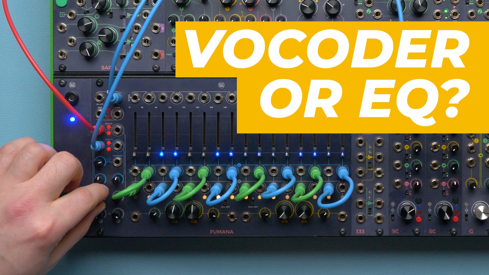
This interface was the main inspiration for our FUMANA, which we’ll see in a moment.
So, is “filter bank” just a fancy name for EQs? Well, not quite. The primary purpose of an eq was initially to restore the audio spectra altered by recording equipment. It made the recorded track equal to the original source, hence the name.
With the development of the mixing technique, EQs were used for more drastic adjustments, but their primary purpose was nearly always the audio fidelity.
On the other hand, Filters were used in analog synthesis to alter the sound timbre deliberately: fidelity was thus not the primary concern.
One can find some practical differences between EQs and filter banks, like EQs usually can boost a band’s signal while filter banks can’t, or the fact that EQs attenuate a band while filters can shut it off completely, but the technical distinction is blurred.
The main difference is thus mainly theoretical: an eq is meant to correct a sound, a filter to change it.
Let’s take our FUMANA and see how it changes our sound. In this video, we’ll show some specific patches: if you want to learn in detail how FUMANA works, stay in touch because we’ll upload a video tutorial next week! When it is out, I will link to it in the comments.
Let’s duplicate a sawtooth with the 333, then patch one copy to the CGM mixer and one to the MAIN input of FUMANA. Then, patch the ALL output to another CGM channel.
We are using this waveform because it is very rich in harmonics, and it will thus pass through more bands. Let’s adjust the gain levels and hear the differences.
We can hear that even with the sliders completely flat, there is a slight difference with the dry sound.
Other common sounds to test this equipment are white and pink noise, and in both cases, we can hear that FUMANA has a more colored sound. Still, if we like this color, we can easily use it to equalize any sound using sliders.
We didn’t use a sine wave because it has only one harmonic, the fundamental: for this reason, it will generally sit only within a single band, thus making the whole filter bank idea rather pointless.
Each slider also has a CV input. We can sum an external voltage and automate the bands’ amplitude: it is summed to the slider position.
Besides many similarities with the 296 interface, FUMANA’s original design has many differences. The most evident is the frequency of each band. We said that there is no fixed rule on that. FUMANA’s bands are a little wider and cover a broader spectrum. This has some pros and cons that we’ll see later on.
We tuned the central bands (2 to 15) roughly 5.5 semitones apart. Why such an odd and apparently unmusical number?
Because if they were tuned to a consonant interval like a fifth or an octave, every sound that would hit that frequency spot would be overly emphasized as opposed to those who don’t.
The purpose of a filter bank is to avoid any resonance and treat every sound equally. Otherwise, we may have a resonator!
The first and last band depart from this rigid scheme: we tune them by taste, according to what sounds best as “sub-bass” and “upper end.” You can read each bands’ upper and lower cutoff frequency between each slider.
However, the Buchla 296 had some clever features that caught our attention:
- The Odd and even distinction
- The “program control” section
- The spectral transferring function.
We implemented some similar features on the FUMANA, but we made some dramatic changes. Let’s go through all of them!
First, odd and even. The original 296 allowed you to split the bands into two groups: odd and even. You could have sent a signal to all the 16 bands and then used the two groups of eight separately. Or, you could have patched two different sounds to the odd and even bands, blending them in the ALL outputs. Finally, you could just have routed two sounds through the two groups and used their independent outputs.
This distinction is also on FUMANA, but with two differences: the inputs are semi-normaled so that if we patch only a cable, it will go through all the bands.
If we want to route a sound differently across the odd/even distinction, we can use the two attenuators without the need to repatch the input cable.
Then, we added an additional lowpass filter at 18 kHz to smoothen the ALL output, but we bypass it when we use the ODD or EVEN outputs so that you can have even more options.
The Program control section on the Buchla allowed you to voltage-control a group of bands in a bell-like shape around a central frequency through two parameters. The first one set the central frequency, and the other set the width of the bell, from one band to almost eight per side. The bands around the selected central one become progressively softer, resembling a bandpass filter with variable frequency.
On FUMANA, we have three parameters instead of two: the first one defines the amplitude of the central frequency, which can also be negative (more on this soon). The Center knob defines the central frequency, and the Width knob determines the spread.
If we set all the faders to the lower position, we can have our fake bandpass filter with variable gain, cutoff frequency, and Q. All these parameters are voltage-controllable.
If we set all the faders to the upper position, we can take advantage of the negative side of the first knob and remove some bands, like a notch filter. This is why this knob is called peak/notch.
The third feature is perhaps the deepest of the 296, the spectrum transfer function, which was mislabeled in some units as spectral bias (like this one).
On the 296, the sound filtered by the 16 bands also fed 16 envelope followers, which followed the amplitude of the sound passing through the corresponding band. With a high amplitude, they output a high voltage and vice versa.
By patching an envelope follower to the CV input of another band, one could transfer the energy of the first band to the second one. When done at a larger scale, this is the working principle of vocoders. That’s why we mentioned them at the beginning!
A vocoder uses two sounds, which we can call “carrier” and “modulator.” The carrier is usually a rich sound like a sawtooth wave, while the modulator is usually a human voice.
The vocoder filters both sounds through two filter banks tuned to the same frequencies. The modulator’s filter bank does not output any sound: instead, it outputs an envelope that follows the signal’s amplitude of that band.
Each envelope then controls the amplitude of the corresponding carrier’s band, which will open and close the bandpass filters’ amplifiers according to the energy of the modulator’s bands.
This is why vocoding is also called spectral transferring: it transfers a sound’s spectral footprint to another with a completely different timbre.
The 296 allowed to transfer the spectral footprint of the odd bands to the even ones and vice versa. By patching a vocal sound and a synth sound to the odd and even inputs, one could have used them as modulators and carriers. It was thus possible to use the 296 as an eight-band vocoder with excellent results. However, since one could have transferred the odd bands over the even ones or vice versa, there was never a perfect match of spectral content, being it offset up or down by one band.
On FUMANA, we have a second array of bandpass filters specific for spectral processing. They are tuned to the same frequencies as the carrier ones, providing a precise spectral transfer.
Let’s try to patch one oscillator to one of the MAIN inputs and another to a MOD one. First, we sweep through the carrier’s spectrum by changing the modulator’s frequency.
If you want to hear something like the classic BUCHLA eight-on-eight spectral transferring, you just need eight patch cables. First, patch them to the envelope follower outputs and reroute them to the desired bands, for example, the odd over the even ones. Then, use the MAIN and MOD attenuators to remove the other side of the carrier and modulator.
If we replace the modulator with a vocal sound, we obtain a vocoder. We can use the two envelope followers’ rise and fall knobs to adjust the response of the envelope followers.
However, we said that we tuned the bands roughly 5.5 semitones apart from each other. This may not be specifically designed for the human voice since some bands are way below the human range. However, it allows you to use any other sound as a modulator, like drums.
The odd/even distinction also works for the spectral transfer circuit. We can use two different sounds to modulate a single carrier’s odd and even bands or use a single sound to modulate two carriers or use the two circuits independently as two eight-band vocoders.
And this is our introduction to filter banks and spectral transferring. To learn more about FUMANA, stay in touch for the tutorial next week! When it is out, I will link it here. I hope this talk was helpful and I’ll see you next time.